Boundaries
Learning targets
- Treatment of boundaries of the computational domain
- Transparent boundaries, periodic boundaries, fixed boundary conditions
- Setting global boundary conditions
Boundary treatment is stated on all edges of the computational domain.
Note
When the specific Priority Priority = -1 (or equivalently Priority=ComputationalDomain) is chosen, all boundary conditions specified to
the corresponding geometrical object will be inherited to overlapping
objects which touch the boundary.
Different types of boundary treatment can be defined:
- For
Periodicboundaries, periodic faces will be segmented in the same way and will be listed as periodic in thegrid.jcmfile. This then allows to specify, e.g., Bloch-periodic wave phenomena on a unit cell of a periodic array. - For a
Transparentboundary, a space region (exterior domain) is added beyond the boundary which models some material which continues quasi to infinity. By default material and geometrical properties of the exterior domain are inherited from the adjacent geometrical objects in the computational domain. - A
Domainboundary allows to fix a physical condition on the boundary of the computational domain. In this case an identifierBoundaryIdis specified which corresponds to a section in the fileboundary_conditions.jcm.
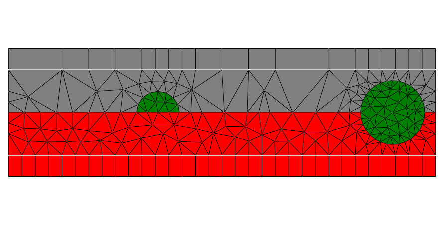
The following layout example contains transparent boundary conditions at top and bottom of the computational domain, and periodic boundary conditions at the left and right boundaries, the resulting geometry and mesh corresponds to the following figure:
Layout2D {
 Objects{
  Polygon {
    Name = "ComputationalDomain"
    Priority = -1
    Points = [-10 -2
               10 -2
               10  2
              -10  2]
    Boundary{
      Number = [1 3]
      Class = Transparent
    }
    Boundary {
      Number = [2 4]
      Class = Periodic
    }
  }
  ...

Note
- The points of a polygon have to be oriented counter-clockwise.
- Boundary conditions are attributed to the segments of the polygon.
The first segment (
Number = 1) connects the first and second point, the second segment connects the second and third point, etc. - Transparent boundary conditions correspond to a model where the exterior space
adjacent to the boundary extends to infinity, such that any scattered light
propagating beyond a transparent boundary is not reflected back. In
JCMviewthe part of the mesh corresponding to exterior space is also visualized (see top and bottom regions with quadrilateral elements in the figure).
Instead of the boundary definition on edges of a geometrical primitive, it is also allowed to define global boundary conditions for axis-aligned geometries. This definition uses the outer normal direction of an edge as a global selection criterion to define boundary treatment on all edges shared with the computational domain. To define the same boundary conditions as above, you can use the following code:
Layout2D {
 BoundaryConditions {
   Boundary {
     Class = Transparent
     Direction = [-Y, Y]
   }
   Boundary {
     Class = Periodic
     Direction = Horizontal
   }
 }
 Objects{
  Polygon {
    Name = "ComputationalDomain"
    Priority = -1
    Points = [-10 -2
               10 -2
               10  2
              -10  2]
  }
  ...
Note that you can select the Boundary via their Direction or using the Direction = Horizontal selector which is equivalent to Direction = [-X, X] in 2D.